| |||
| 1. | Disconnect the negative battery terminal | 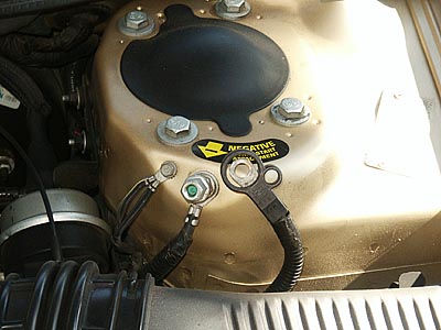
| |
| 2. | Remove the trim around the radio and temperature controls. This just pops out, being held by four clips. Remove the trim bezel by grabbing the inside edges near the tab locations and pulling straight forward. Don't bend it and break it! | 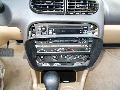
| |
| 3. | Remove the fuse cover on the left end of dash. | 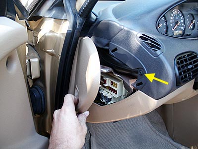
| |
| 4. | Remove one (1) dash cover screw from inside fuse area | ||
| 5. | Remove four (4) dash cover screws from the radio and temp control area. There are two on each side. | 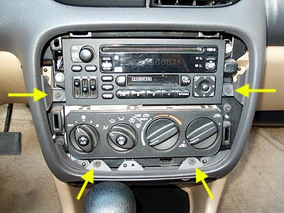
| |
| 6. | Lower the steering wheel to the lowest position | 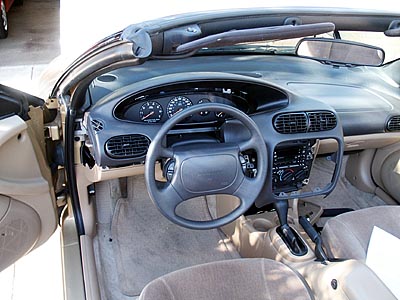
| |
| 7. | Remove the dash cover by pulling straight out. There are four (4) clips that must be carefully disengaged. I found that when pulling the cover straight towards me while sitting in the driver's seat, the clips disengaged very easily. (Note: if your car is equipped with the temp/directional computer you will need to pull the dash cover away about 2-4 inches. Then reach up through the radio/temp control area and disconnect the plug that attaches to the temp/directional computer). Set dash cover aside, being carefuly not to scratch it. | ||
| 8. | Remove the instrument cluster by removing four (4) screws (two on top and bottom). Now pull straight out on the instrument cluster. | 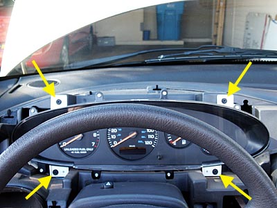
| |
| 9. | Disconnect the two plugs on the backside of the instrument cluster. This is a bit tricky, due to the retaining clips on the back of the connectors. Use a medium screwdriver to pry the clip away from the body of the connector, while simultaneously backing the plug out. | 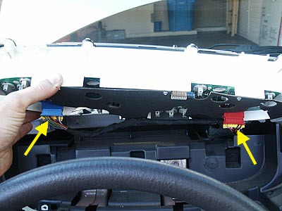
| |
| 10. | The cable harness is held to a cardboard backing with the cable tie/clamp. Instead of cutting this loose, use a Torx screwdriver or small Allen key wrench to remove the six (6) silver screws holding the cardboard backing in place. This will allow you to remove the instrument cluster. Once the instrument cluster is free from the vehicle, be careful not to scratch it. Whenever setting the cluster aside, be sure to do so with it facing upwards. | 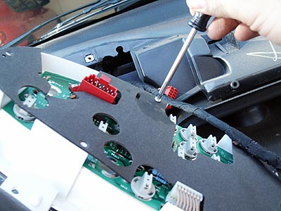
| |
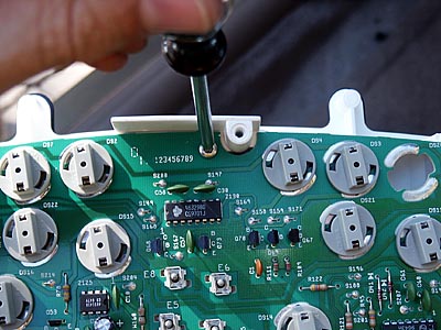
| 11. | On
the instrument cluster circuit board, you'll see eleven (11) silver
colored screws, remove all of them using your Torx screwdriver/Allen
key wrench.
NOTE: On some models, there are only nine (9) screws. |
| |
| 12. | Unplug the circuit board from the instrument cluster. | 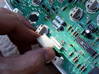
| |
| 13. | Remove the circuit board CAREFULLY from the instrument cluster. The cluster gauges "plug in" to the circuit board. You can see the gauge pins sticking through the board into their respective sockets. It isn't difficult, but you don't want to inadvertently overflex the board and break anything - that would be roughly a $400.00 mistake! | 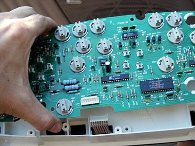
| |
| 14. | Look for three blue resistors on the circuit board; two large and one smaller. Notice also the discolored area on the board around them, due to the heat these resistors generate. The problem is caused by the heat from these resistors gradually breaking down the solder connection to jumper S210 (circled), which connects the front of the circuit board to the rear. You can see the cracked area around the connection in the magnified inset. | 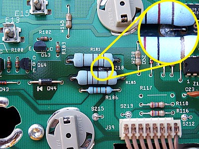
| |
| 15. | Flip the circuit board over and inspect the connections to these resistors and jumper S210 on the underside. You'll probably see a few more dull, cracked solder joints. | 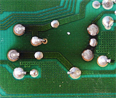
| |
| 16. | Warm up your soldering iron, and use a good-quality 60-40 rosin core solder to touch up all solder joints associated with these resistors and jumper S210. | ||
| 17. | Use plenty of solder to create "domed" connections, as shown at right. Use isopropyl alcohol and some cotton swabs to clean up the excess flux from around the solder joints. | 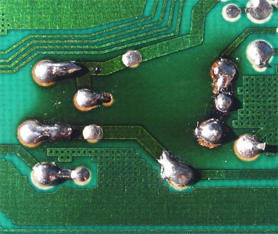
| |
| 18. | Finally, and most importantly, don't forget to touch up the top S210 jumper solder connection. This is the one that's subjected to the most heat, and is probably the joint in the worst condition. If you have to, temporarily desolder and remove one of the leads to resistor R105 so you can swing it out of the way and do a good job resoldering this crucial connection. When you're done, it should look like the picture on the right. | 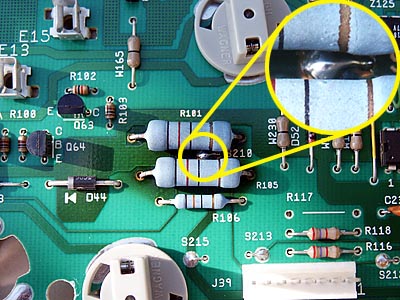
| |
| 19. | Once the connections have cooled, reassemble the instrument cluster, and reverse the above procedure to reinstall. My odometer and tach haven't so much as blinked since I completed this repair. Thanks to Russell Wright and Martin Mackes for taking the time to post this fix - you guys saved me at least $500.00 over what my dealer would have charged me! | ||
| Any further
questions, post here or e-mail me at dpeters30@cox.net Good luck, and let us know how it goes! -Dave | |||