Main power supply filter capacitors in audio equipment have primarily a dual function - one is
to filter out any ripple from the bridge-rectified DC, which would otherwise
manifest in your audio as a 60Hz or higher-order harmonic hum. The second
function is almost like a set of storage batteries - once the big caps charge
up, they resist changes in voltage. So, if you're playing a particularly
demanding passage with lots of transients for example, it tends to exhaust the
capabilities of the power supply, and voltage tends to "sag". The big filters
don't like this change, and supply their own stored current to the circuit
(they 'discharge'), shoring up the power supply's voltage, so the demanding passage
may be reproduced cleanly and without distortion.
Older filter caps start to "leak", or lose their ability to hold a charge, and
since they aren't as good at keeping the supply voltage constant, distortion
tends to increase, and usually manifests as weak, or "muddy" bass response. If a
filter cap is really on the ropes, you may even start to notice hum, even with
the volume control all the way down. Bottom line, if you want a 30+ year-old
receiver to sound like it should, you need to replace those ancient filter caps.
Replacing the rest of the electrolytic capacitors in the unit will provide
further improvement, but the lion's share of benefit will be realized when you
refresh those main filters.
Replacing the main filter caps in a vintage receiver is usually a fairly straight-forward operation. Find new filters of approximately the same size, pull the old filters, and solder the new filters in. Unfortunately, on some of the larger Marantz receivers, it ain't so easy - because Marantz engineers, perhaps as a space-saving measure, decided to employ "dual-section" filter capacitors in these units. These dual section caps are actually two separate electrolytic capacitors contained in the same housing, connected by a common terminal. For whatever reason, these dual-section caps are no longer manufactured, so there are no easy drop-in replacements available. I learned about the possibility of creating custom-made replacements for these obsolete components on the AudioKarma vintage audio forum, and leveraging the expert experience and kind advice of fellow forum members, arrived at the procedure shown below.
The process basically involves removing the old filter caps, cutting them open, and stuffing them with modern capacitors that, due to modern manufacturing advances, can provide similar or greater capacitances in much smaller packages. The original filter capacitors used in the Marantz 2600 are dual section 7,200µF components at 105 working volts DC (WVDC). These capacitors were specially made specifically for the 2600, and have been obsolete for decades. Making matters worse, to this day, NOBODY manufactures electrolytic capacitors designed to handle 105 WVDC. 100 WVDC, sure, but that's not quite enough - and the next step is 160 WVDC, too physically large to be useful. However, Panasonic now manufactures a low profile series of electrolytic caps known as the "TS-HC" series, and it turns out they manufacture an 1,800µF, 160WVDC version (Mouser part #667-EET-HC2C182CA, as of this writing), just small enough that eight of them can be contained within one of the original Marantz filter cap cans. Connected properly, that's two separate sections of 4 x 1,800µF or 7,200µF each, running at 160 WVDC - plenty of working voltage to spare. Adding some 'icing on the cake', the new Panasonics can handle a 23% hotter working environment as well. We have a winner!!
As the original Marantz dual-section filters are rarer than hens' teeth, and those in this particular 2600, though weak, were still functional, I couldn't bring myself to destroy them in order to install the internal replacement Panasonic caps. As it happens, I had some old Nippon Chemicon filter caps from the previous restoration of a Pioneer SX-1250 receiver, and they just happened to be exactly the same diameter as the Marantz filters. Even though they utilized two screw terminals rather than the three-solder-lug design of the original filters, I decided to use them anyway. I'm very pleased with the results. Here's the procedure:
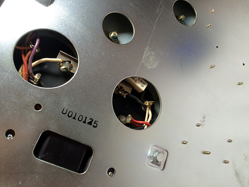
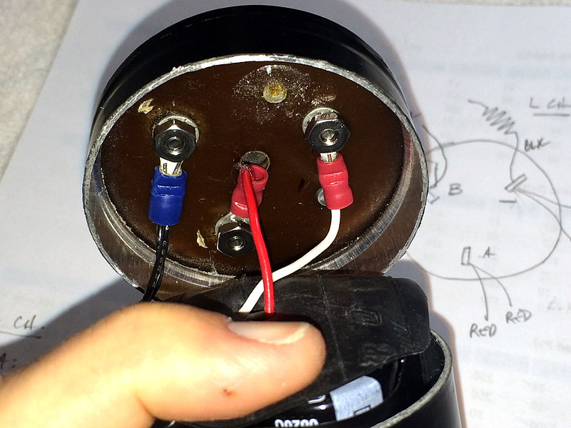
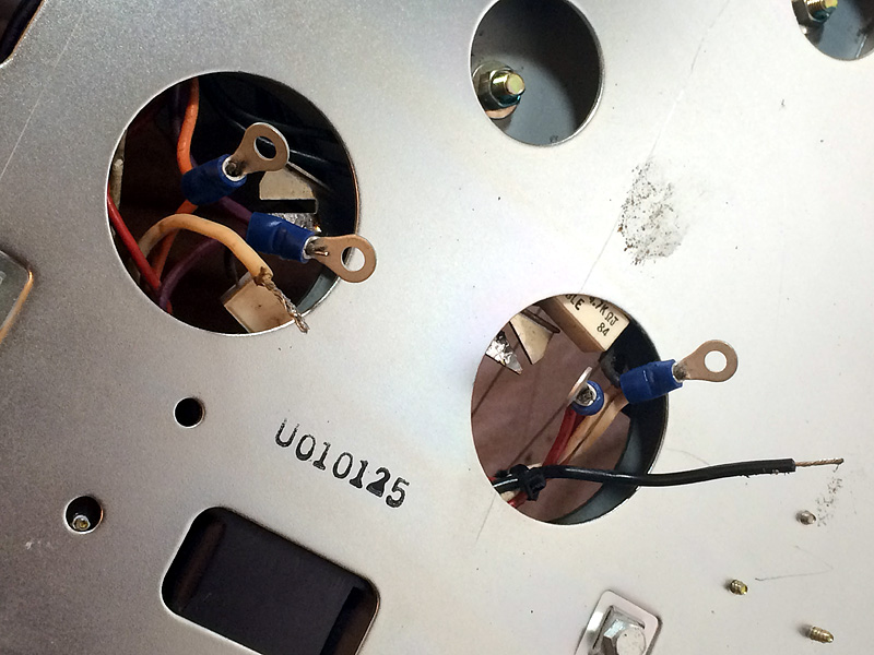
First things first. Make a detailed diagram showing the wiring to the existing filter caps. Each dual-section filter has a terminal marked "A", a terminal marked "B", and a terminal marked "-" (common terminal). These designations are stamped into the rivet for each terminal. Make sure you capture what color wires are hooked up to what terminal for each channel. Be careful, the common terminal DOES NOT connect to the ground strap!
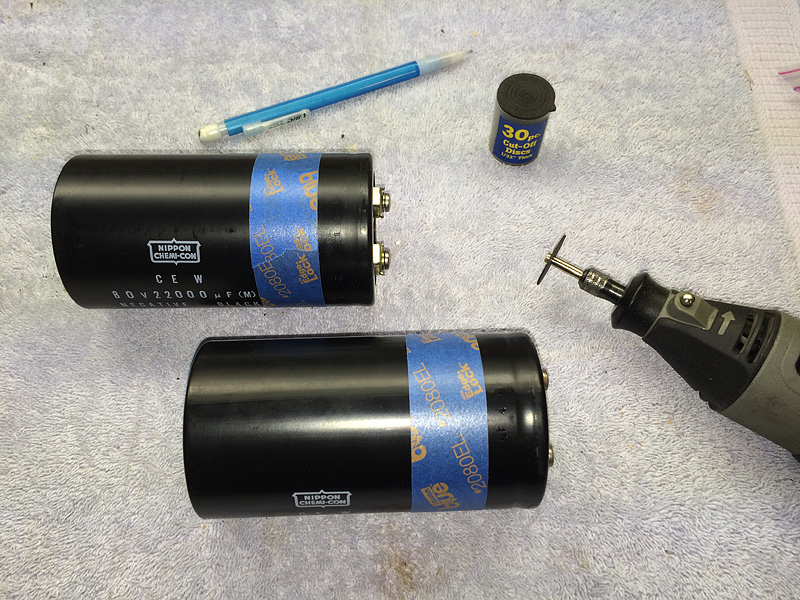
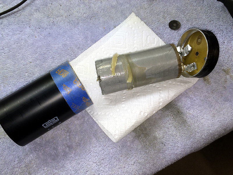
Now that your connection diagram is complete, it's time for surgery. You want the cut line to fall in the middle of the area covered by the clamp when the cap is installed. IMPORTANT: Since the screw terminals add about a 1/4" to the final height of the replacement, make sure the clamp is shifted down to compensate before marking your cut line. Take your replacement filters and mask your cut lines. This makes it easier to keep the cut line parallel to the edge of the capacitor and makes it much easier to see as you cut.
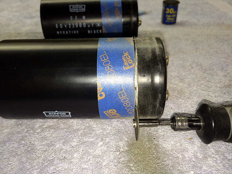
Cut open the old filter. A Dremel tool with cutting wheel works well for this.
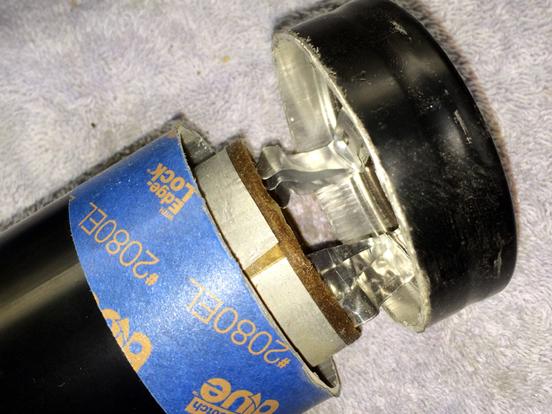
Cutting complete. Take note of the rivets connected to the foils - these will be drilled out later on.
The disassembled filter. Have some absorbent material ready to soak up any excess electrolyte that may leak out.
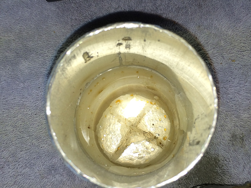
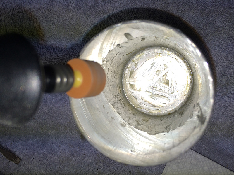
In this particular capacitor, the substrate is held in place with a wax-type substance.
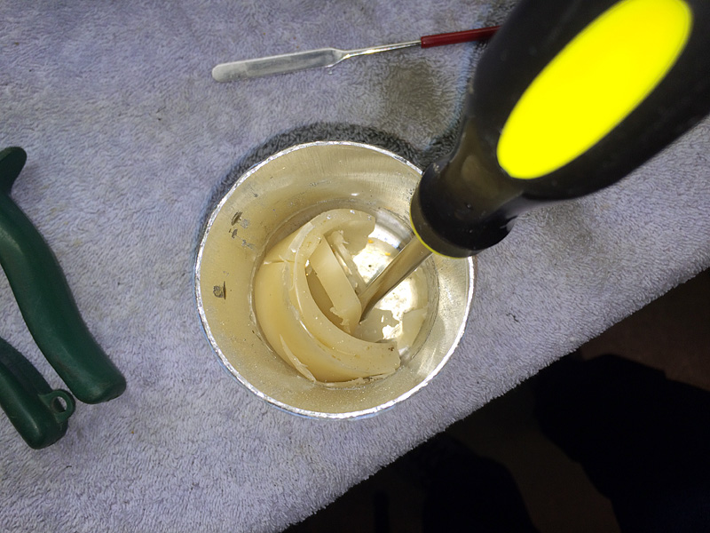
Break up the wax with a small screwdriver and remove it. Scrape out as much as you can.
A view of the cleaned out can.
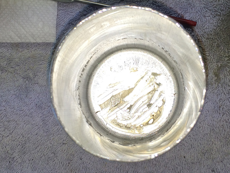
It's a good idea to de-burr the edges with a file, some sandpaper, or a grinder attachment so you don't cut yourself as you work with the cans.
Once the replacement cap cans are cleaned out and de-burred, it's time to assemble the internal capacitor arrays. Group them in four sets of four, taking care to keep the negative terminals on the outside corners. Tape them together with electrical tape as shown. As each capacitor is rated for 1,800µF, connecting four of them in parallel will give us the required 7,200µF. As an added bonus, while the old capacitors were rated at 105 working volts DC (WVDC), perilously close to the amplifier section's actual rail voltages, these new caps can handle 160 WVDC - a much more comfortable margin of safety. Finally, the new caps are also rated to handle significantly more heat than the old ones - 105°C compared to 85°C (221°F vs. 185°F). Definitely an upgrade worth the few hours spent!

Solder the positive (inside) terminals of the capacitors together as shown. If you're clever, you can do this using one unbroken piece of solid-core 20 ga. wire. Solder as close to the bottoms of the terminals as possible, as we need to conserve vertical space. Repeat for the negative (outside) terminals. Color-code your wires so you know which is which. Leave enough wire on the lower array so you have 4-5" to work with above the edge of the can once the array is in place. Once all soldering is complete, clip off the tops of the capacitors' terminals so you have nice flush connections.
Lower the first array into the first can. Make sure you have enough lead wire sticking out of the can to work with (4-5").
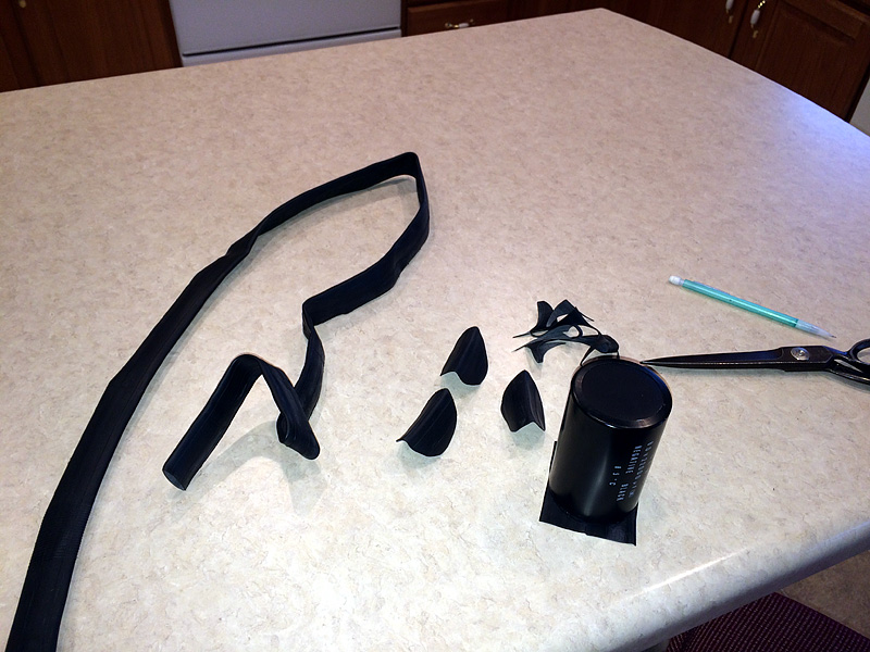
Now we need to create an insulating barrier before we install the upper array. There's a certain amount of insulating plastic wrapping on the new capacitors anyway, but a little added insulation is certainly prudent, considering the high currents flowing through these replacement capacitors. Remember, the material you choose should be thin but effective, and should be durable enough to last several decades. I selected sheet rubber for its excellent insulating properties, its durability over time, and its ability to provide some cushioning for the internal arrays. I obtained a fresh new bicycle tire inner tube and cut it into four circular pieces just large enough to fit inside the cans.
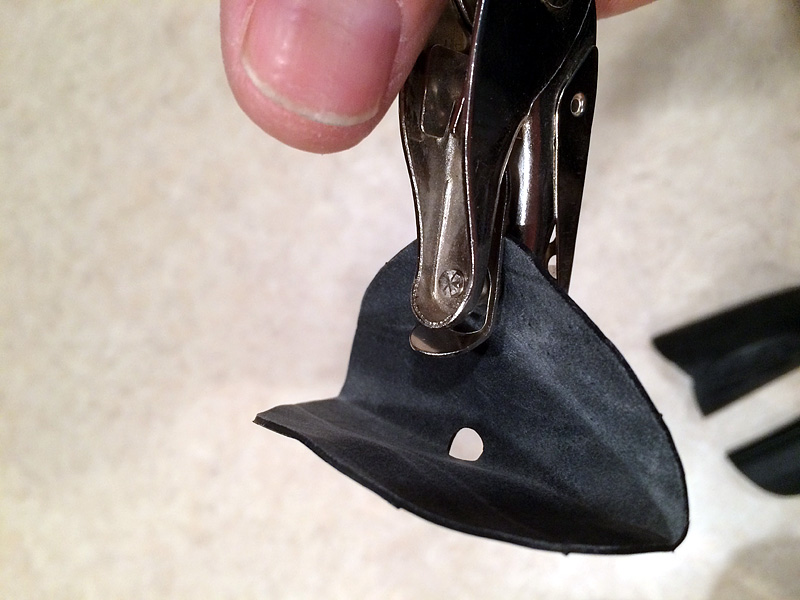
Use a standard hole punch to punch two holes for the wires - a center hole for the positive wires and a hole off to the side for the negative wires.
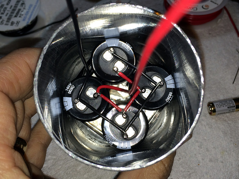
Place the insulator over the lower array and route the wires through the holes as shown.
Now, install the upper array such that the positive wire from the lower array routes through the center of the upper array, and the lower negative wire routes next to that of the upper, as shown.
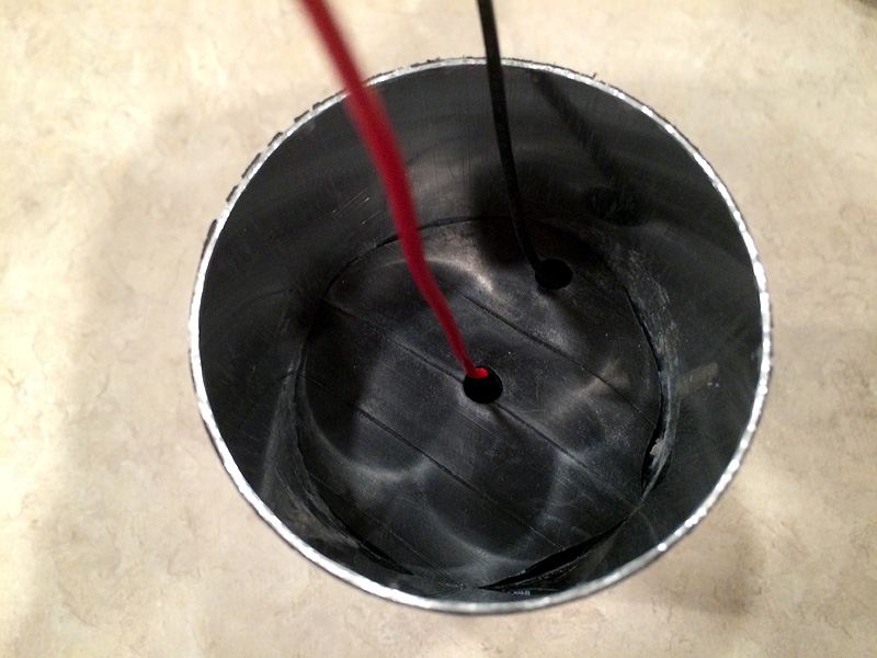
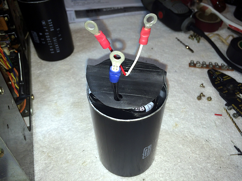
Install another rubber insulator over the top array, routing the wires as shown below. The red wire represents section "A", the white represents section "B", and the two black wires are tied together to form our "-", or common. Trim your leads down to about 3" and strip the ends.
Obtain some ring connectors at your local hardware store and crimp them to the wires as shown.
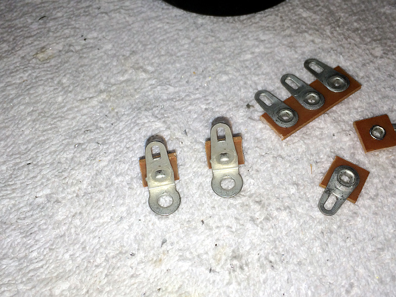
Now, it's time to prepare the top sections of our replacement filters. Since the original filter caps we've selected have only two terminals, we need to install a third. Since one of the terminals needs to be soldered to the 2600's filter connection grounding strap, a solderable terminal strip is a good choice. These can be had cheaply via eBay or any online electronic supply house; I obtained some 7-lug strips and cut them down to the two mountable sections shown below.
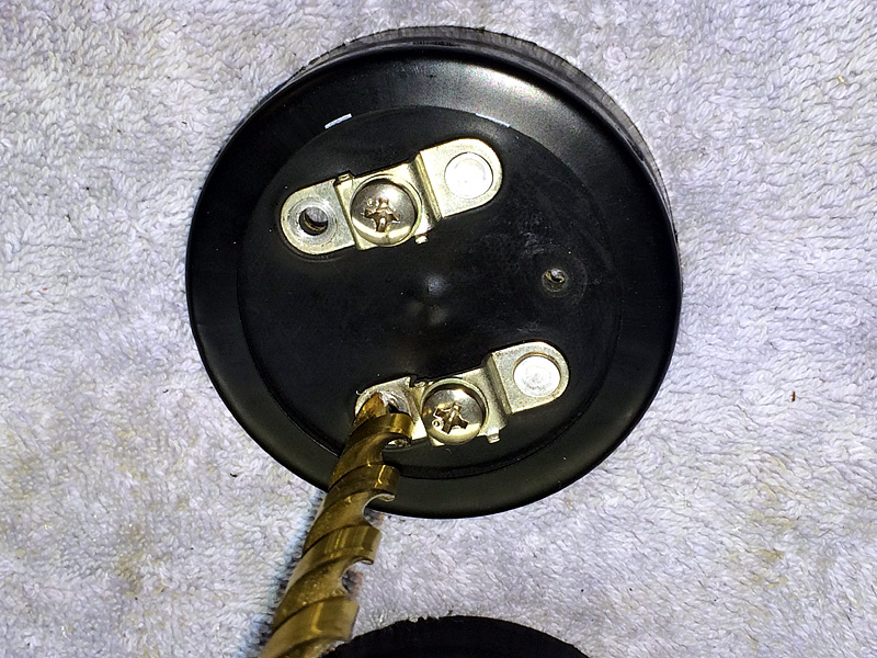
Position the terminal lug midway between the existing screw terminals of the replacement can and drill an 1/8" hole, as seen below. Next, locate the rivets that were connected to the foils going to the original innards, and drill them out.
Using some 1/2" 6-32 screws, nuts, and some external-tooth lock-washers for a good "bite", connect your spade lugs to the corresponding terminals through the three holes you created in the previous step. BE VERY CAREFUL HERE. Using the diagram you created in the first step, ensure that your black common wires are connected to the screw terminal that, when the new filter is installed, corresponds to those wires in the 2600 that originally connected to the "-" section of the old filter. The solderable terminal you added MUST be connected to one of the positive array wires (doesn't really matter which), and the remaining positive array wire will connect to the remaining screw terminal. Check, double-check and triple-check that you get this right. You can seriously damage your receiver if you get it wrong!!
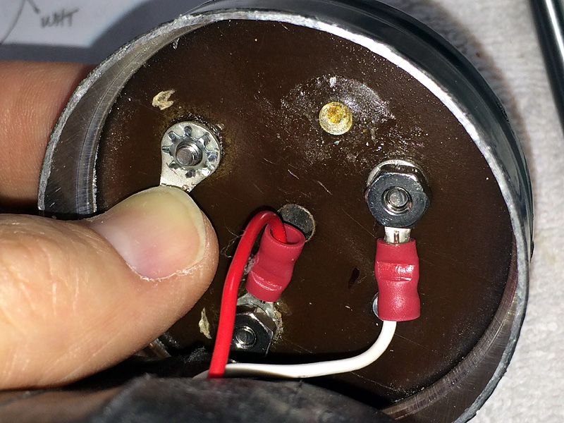
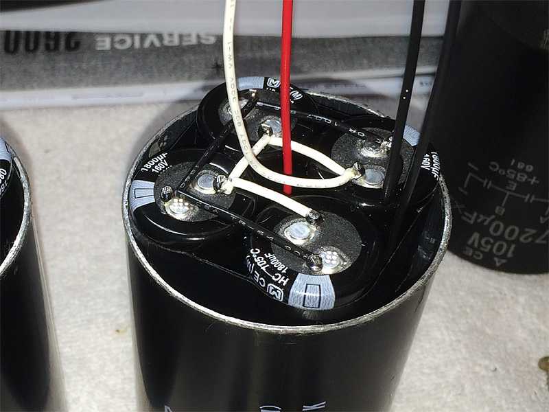
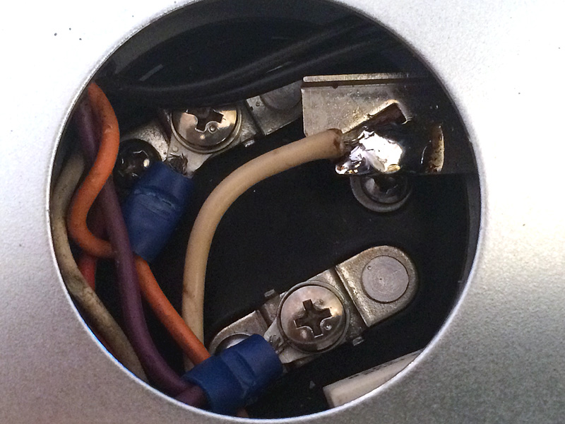
Here are the connections, snugged down good and tight. The upper array positive (white) is connected to the new solderable terminal. The common (black) is connected to the screw terminal corresponding to the wires in the 2600 that were originally connected to the "-" terminal of the old filter. The lower array positive is connected to the remaining screw terminal. You can see part of my connection diagram in the background.
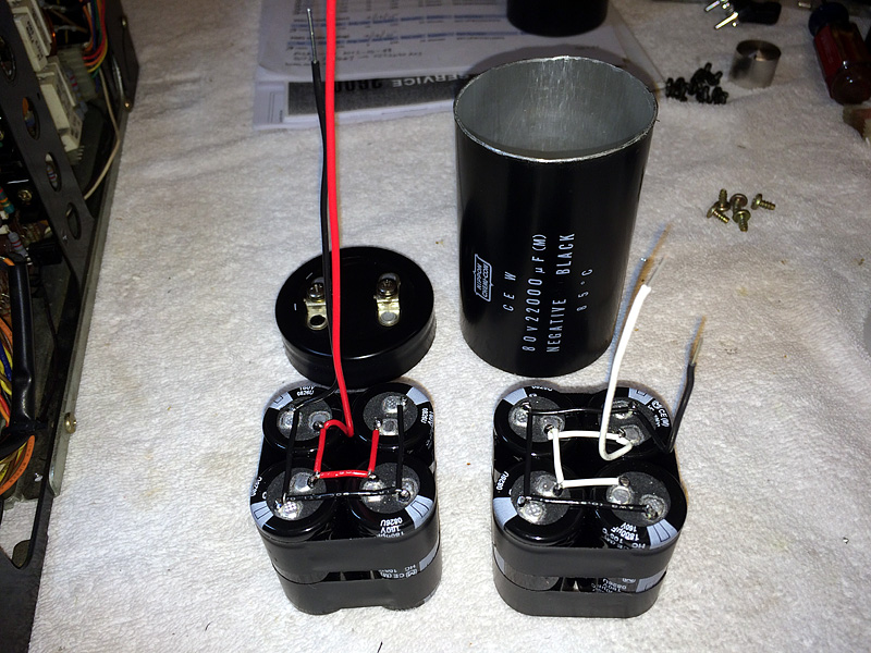
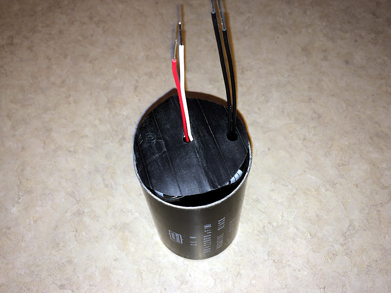
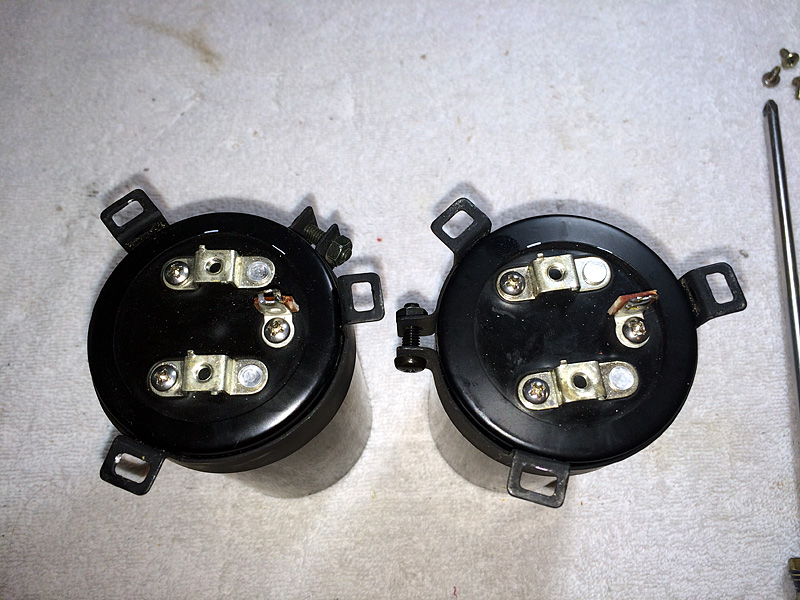
Once the internal connections have been completed and verified, tape the cans back together using two turns of electrical tape. If you conserved your vertical space well, the ends should just fit together. However, if you have a little gap, it's no big deal - the mounting clamps will hide any small gaps up to about 1/4". Below are the completed dual-section filters, looking down on the terminal configurations.
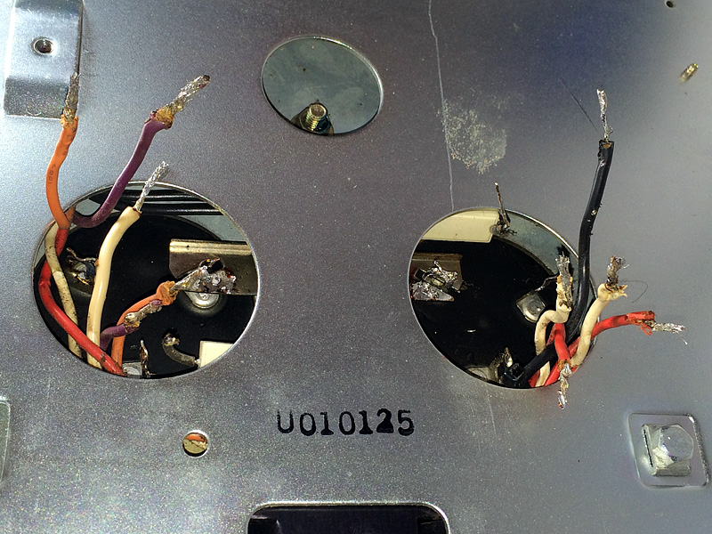
Okay - time to remove the old original filter caps. Try to salvage as much of the original hookup wire as possible, as you don't have much to work with.
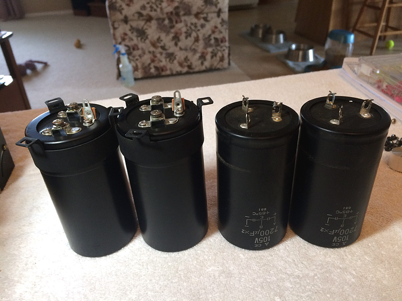
Here's a shot of the new filters stacked up against the old. The new ones are exactly the same diameter, but just a shade taller. That's okay - we have plenty of extra vertical space in the 2600, if necessary. Notice how the clamps on the new filters are offset a bit, to accommodate the added height of the screw terminals and the solderable lug.
Crimp ring connectors onto the wires that will be connecting to the screw terminals on the new filters. The two remaining wires (black and white, in this case) will be soldered to their respective ground strap terminals.
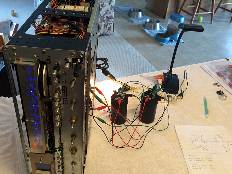
Before we go through the final step of mounting, connecting and soldering in the new filters, it's a wise idea to jumper them into the circuit and make sure everything is functioning properly. MAKE SURE TO USE A "DBT" (Dim Bulb Tester) DURING THIS STEP! You'll want a big bulb for your 2600's DBT - 200 Watts is about right. The DBT will save your receiver if you make a connection error. If the bulb glows brightly and you don't hear any relay clicks from the receiver after five seconds or so, immediately disconnect power and recheck your wiring. Otherwise, if the bulb glows brightly, then quickly dims down and your receiver's relays kick on, you're good to go.
If your 2600 powers up properly on the DBT, it's time to install the new filters. Orient them so that the solderable lugs fit into the slots on the grounding strap and make your connections. Again, MAKE SURE the common terminal is connected properly!! Bend down the solderable lug snug with the grounding strap and solder it well. When you're done, don't take any chances - bring the 2600 up on the DBT. If the bulb dims as it should and your relays click in, you're done!
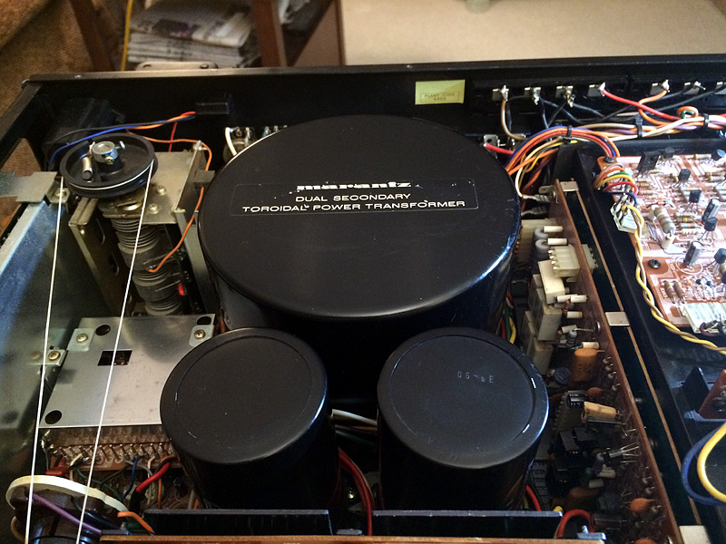
Here's a final shot of the new filters, in place. Even though they're a tad taller than the old filters, they're still shorter than the power transformer, and look just like the originals.
Congratulations! You've probably just made the single most important improvement to your 2600's performance AND longevity. Some folks would advocate running your receiver at a relatively low volume for the next five to ten hours to allow the new filters to "settle in". I'm not sure this is really necessary, but after all the work you just put in, perhaps it's prudent to err on the side of caution. Enjoy your Marantz!!