Marantz SD9000/SD8000 Compudeck Optical Sensor Repair
Overview
Initially offered in 1980 as the flagship of the Marantz cassette deck line, the SD9000 Compudeck was one of the best-built, most feature-packed cassette decks ever offered for consumer use. Retailing at $900.00, the SD9000 utilized two DC servo motors for precision tape control and three heads for direct tape-to-source comparison as you recorded. Way ahead of its time, the SD9000 also incorporated an advanced microprocessor-controlled music search feature, allowing you to program which songs on a given cassette you wanted to listen to, as well as the order in which you wanted to hear them. The SD9000 also offered a digital function for automatic timer recording or playback - accurate to the minute. In addition, the SD9000 included a slew of other advanced features like bias fine adjustment, an auto tape slack removal circuit, mic/line mixing, electronic timer memory, solenoid-controlled feather-touch full logic transport, and the list went on. The Marantz SD8000, a slightly more economic choice, shared virtually all the features of the SD9000, however in a two-head design.
A Fatal Flaw?
Unfortunately, over the years, the SD9000 and its little brother, the SD8000 proved to have an "Achilles Heel". Both decks used a pair of optical sensors to generate the reel turn count pulses for their on-board microprocessors. This microprocessor also interpreted lack of these pulses as a signal that the end of the cassette had been reached, and would send an "all-stop" command to the transport 1.5 seconds after pulse cessation. After ten years or so, depending upon use, these optical sensors (also known as 'optocouplers') would weaken and fail. The symptom? After one or two seconds in any mode, Play, Rewind, or Fast Forward, the deck simply returns to the Stop mode. Over the course of 30+ years, the failure percentage of these optocouplers approaches 100%. Worse than the almost certain failure of these key components is the fact that the original replacement optocouplers are no longer available, rendering these expensive cassette decks essentially useless.
Fortunately, these decks can be brought back to life with commonly available substitute parts, an hour or two of work, and a little patience. Here's how:
Tools/Supplies You'll Need:
- Soldering iron - a smaller 15-20 watt iron is ideal
- Solder - "60/40" or "63/37" rosin core is the stuff you want (never use acid core solder for electronics!)
- Solder wick - get this at Radio Shack or your local electronics supplier
- 90% isopropyl (rubbing) alcohol
- Q-Tips - about a dozen or so
- #1 and #2 Phillips screwdrivers
- Small #1 or jeweler's flat-head screwdriver
- "T10" Torx screwdriver or 2.5mm hex key (Allen) wrench, or 3/32" hex key wrench - any of these will work
- Small wire cutters (I use an old toenail clipper!)
- Long-nose pliers
- Regular pliers or small crescent wrench
Parts You'll Need:
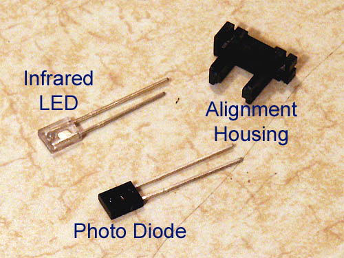
Optek makes an optocoupler with suitable specifications in all criteria for this application except for physical size - it's too large (full manufacturer's data sheet is here). We'll need to modify it as will be seen later. Go to www.mouser.com, and in the "Part# / Keyword" search box, enter the following part number: 828-OPB818, or click here. Order at least two; at approximately $3.00 each, I'd order a few extra for spares, just in case you damage one during the modification. Mouser has no minimum purchase, and the USPS Priority Mail shipping option they offer will get you these parts quickly and cheaply.
By the way - it probably isn't a bad idea to order replacement belt and idler tire kits for your deck while you're waiting for your optocouplers, since you'll be deep into your tape transport anyway. I've ordered several sets from Bob Toepfer at Vintage Electronics with excellent results. As of this writing, current price for the belt kit is $15.00 and $30.00 for the idler tire kit. Not exactly cheap, but I believe these decks are certainly worth the investment.
The Fix:
|
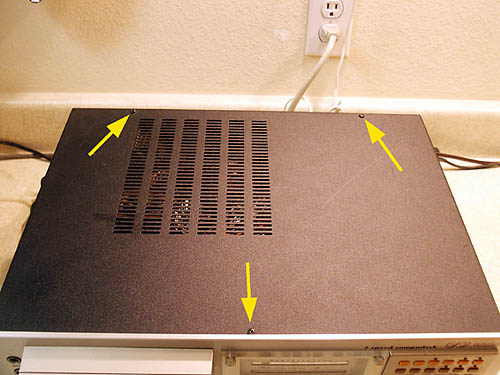
Step 1 Okay, let's get down to it! Start by removing the top three case screws with your #2 Phillips, as shown: |
 |
|
|
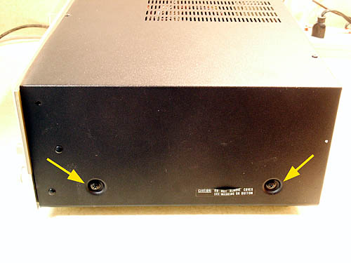
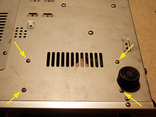
Step 2 Next, remove the two case screws on each side: |
 |
|
|
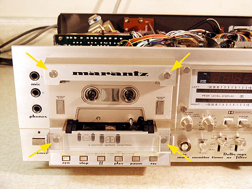
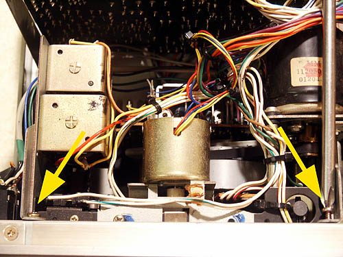
Step 3 Remove the outer metal case and set it aside. Remove the hinging plastic tape head shield (if you're lucky enough to still have one). Remove the knurled finger screws from the front panel (see yellow arrows). These screws secure the top metal "Marantz" panel and the lower clear plastic head adjustment cover - remove them and set them aside. |
 |
|
|
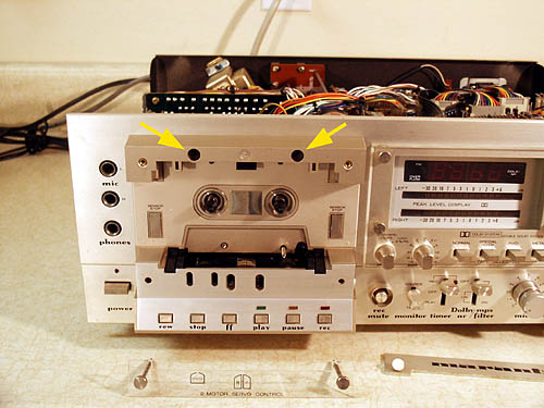
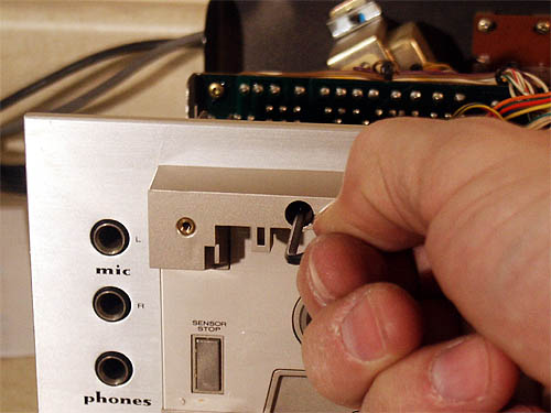
Step 4 Remove the two recessed Torx screws holding the plastic cassette housing assembly in place (see arrows). |
 |
|
If you don't have a T10 Torx screwdriver handy, a 2.5mm metric hex key wrench will work. If you only have English hex key wrenches, a 3/32" will be a bit loose, but should still work. |
 |
|
|
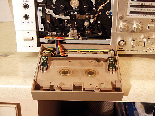
Step 5 Tilt the cassette housing forward (catch the Torx screws you just loosened as they fall out), and set the assembly flat, as shown. |
 |
|
|
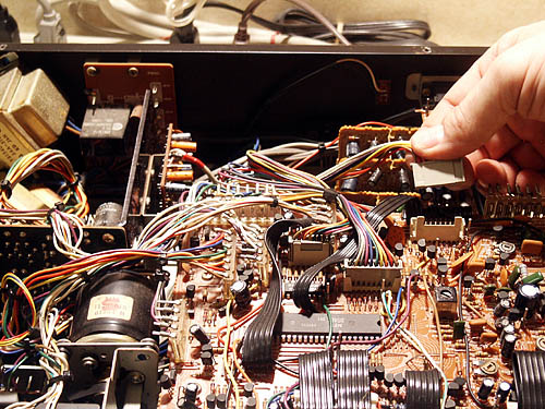
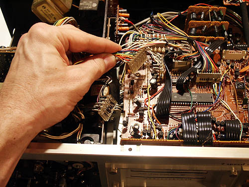
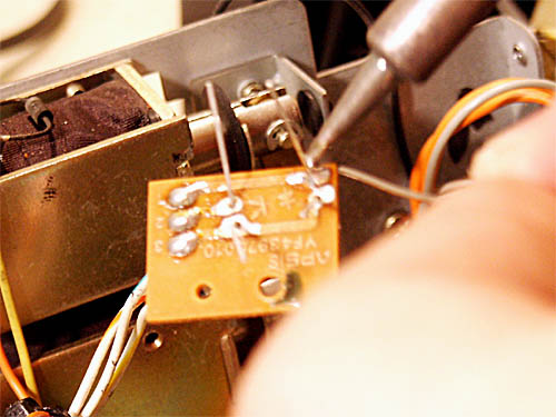
Step 6 Locate plug P508 on the main control board as shown, and unplug it. This is the connector for the cassette housing switch panel you just removed in step 6. |
 |
|
|
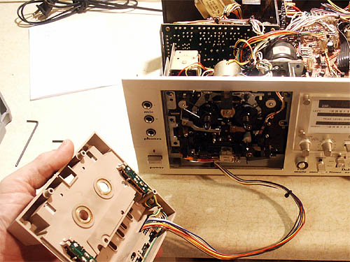
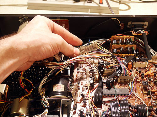
Step 7 Thread the P508 connector down through the other wiring while gently pulling on the cassette housing, as shown. You may need to cut some wire ties to do this. Fish the connector through the opening below the cassette transport mechanism and set the entire plastic cassette housing aside. |
 |
|
|
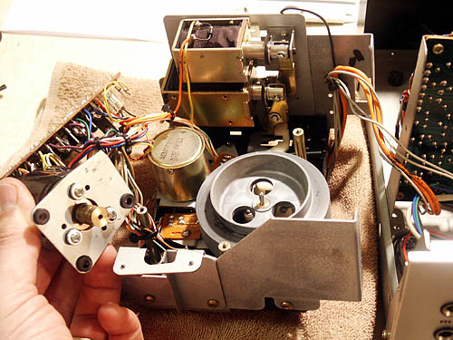
Step 8 Remove the two cassette transport assembly securing screws, as shown. |
 |
|
|
Step 9 Flip the deck over and remove the four remaining screws holding the tape transport in place, as shown. |
 |
|
|
Step 10 Turn the deck right-side-up again, and locate plug P503, as shown. Remove it gently. Always grasp the plug body, not the wires, when pulling. |
 |
|
|
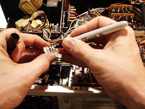
Step 11 It's a really good idea to mark the connector designations on the connectors themselves, since it is possible to plug a connector into the wrong receptacle on this model! |
 |
|
|
Step 12 Remove and mark connector P502. |
 |
|
|
Step 13 Next, remove and mark connector P501. |
 |
|
|
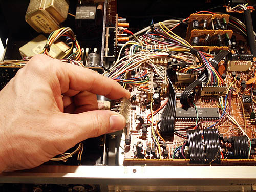
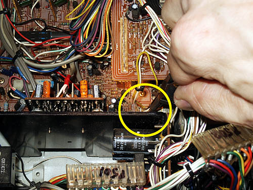
Step 14 The last connector, P206, is located on the lower board, below the microprocessor board. Resist the temptation to just yank on the wires, and use your long-nose pliers to disconnect it. |
 |
|
|
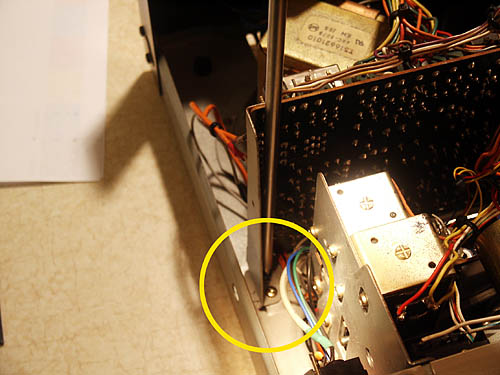
Step 15 To give yourself enough room to maneuver the tape transport out of the deck where you can work on it, you'll need to remove the four Phillips-head screws holding the power supply board in place. The first two are shown here. |
 |
|
|
Step 16 Remove the third power supply board screw, located between the power supply board and the microprocessor board. |
 |
|
|
Step 17 Remove the last power supply board screw, located towards the rear of the deck, between the power supply board and the microprocessor board. |
 |
|
|
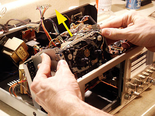
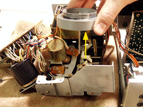
Step 18 Gently move the tape transport assembly towards the back of the deck, then up and out, so that the reel hubs clear the opening in the deck's front panel. |
 |
|
|
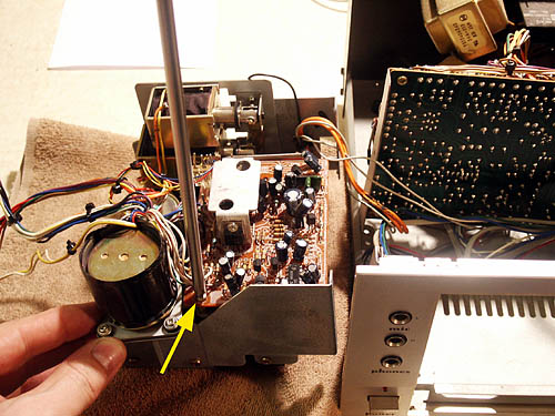
Step 19 Lift the transport clear of the chassis and place it on a towel to prevent it from being scratched. The signal wires from the record/play/erase heads will still be connected; be careful not to place stress on them as you maneuver the transport. Remove the Phillips screw securing the motor driver board to the transport housing. |
 |
|
|
Step 20 Tilt the motor driver board up and pull it towards you (as in the picture) to remove it from the slotted retaining clip on the far side of the board. |
 |
|
|
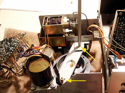
Step 21 Remove the Phillips screw securing the motor driver board retaining clip, and then remove the clip. Use a standard pliers to remove the brass threaded hex bushing (lower arrow), and remove the flywheel retaining bar. |
 |
|
|
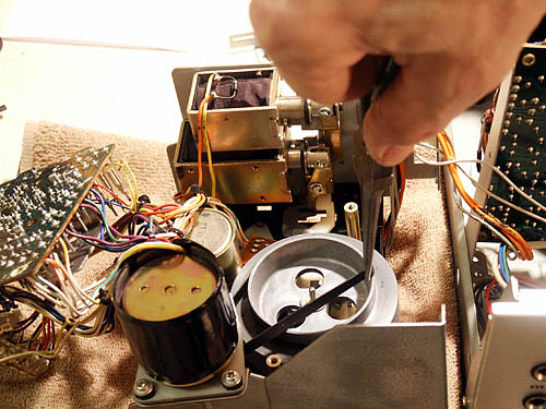
Step 22 Remove the flywheel drive belt with a pair of long-nose pliers that has been cleaned with a rag dipped in 90% rubbing (isopropyl) alcohol solution. Try to avoid touching the belt if possible - the idea is to keep any grease on the pliers or oil from your fingers from getting on this belt. |
 |
|
|
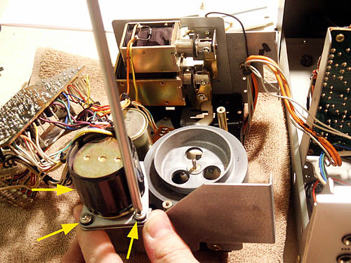
Step 23 Next, remove the three Philips screws holding the capstan motor assembly in place. |
 |
|
|
Step 24 Lift the capstan motor free of the transport assembly, and set it to the side. Now would be a good time to clean the capstan motor pulley with some swabs dipped in your 90% isopropyl. |
 |
|
|
Step 25 Pull the flywheel up and out of its bearing, twisting gently side to side as you exert upward pressure. Notice the belt residue on this particular flywheel - unless yours is perfectly clean, use swabs and 90% isopropyl to remove all traces of residue. |
 |
|
|
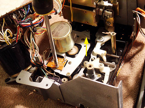
Step 26 At last, we have access to the two optocoupler boards (see yellow arrows). Before you remove the board nearest the solenoids, scribe a pencil line (see red arrow) along the outer edge to capture the correct mounting angle to facilitate reinstallation. |
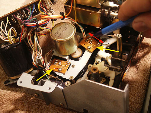 |
|
|
Step 27 With your smaller #1 Phillips screwdriver, remove the optocoupler board nearest the solenoids. There's a washer underneath this board used to properly space the optocoupler away from the reel hub. Make sure you don't drop it into the transport when you remove the board. |
 |
|
|
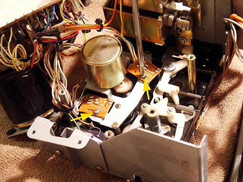
Step 28 Remove the second optocoupler board. This one has no washer below it, and it has a positioning "key", so you don't need to scribe the mounting angle as on the previous board. You can see the mounting angle mark for the first board (yellow arrow). |
 |
|
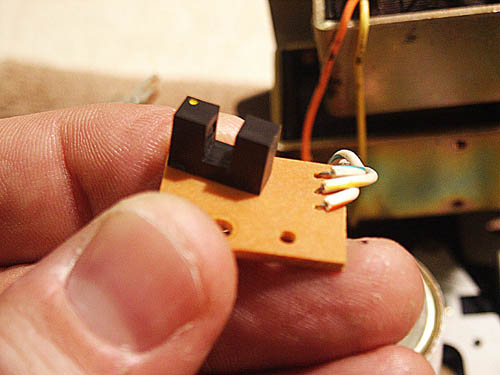
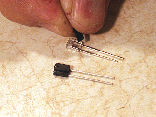
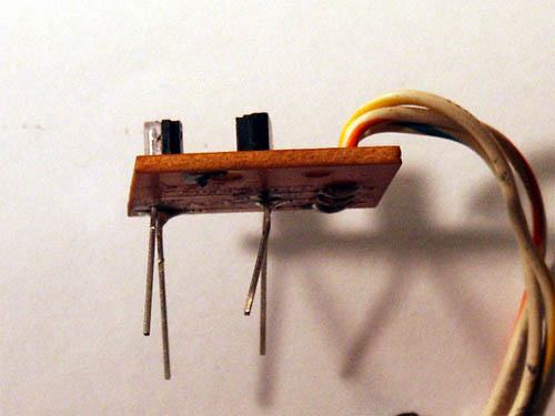
| Here's the culprit - one of the two defective optocouplers. |
 |
|
|
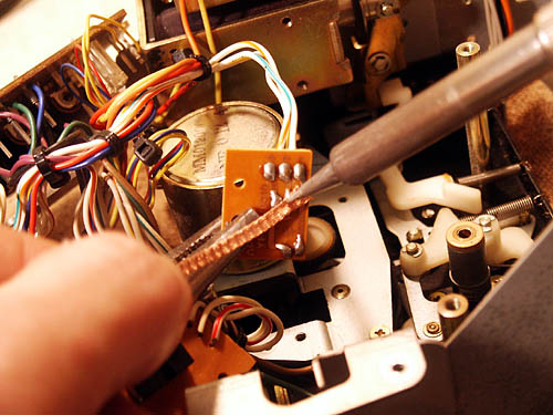
Step 29 Desolder the four connections holding each optocoupler to its board. Solder wick greatly facilitates this process by soaking up the excess solder. |
 |
|
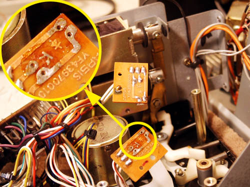
| Here's a detail shot of the optocoupler board traces. Note the photo diode and LED symbols; you'll need to refer to these later when you install the new components. |
 |
|
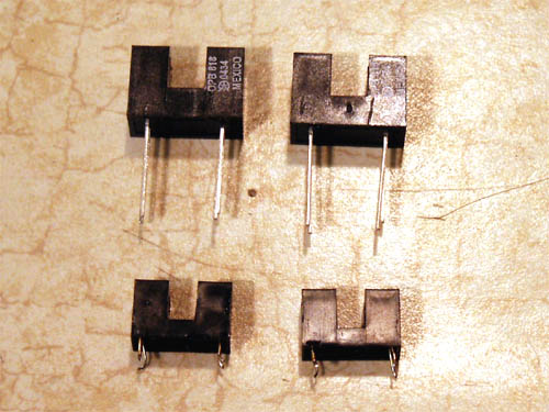
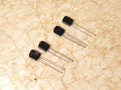
| Note the size difference between the original parts (at bottom) and the replacements. Since the replacements are way too large to be mounted as they are, we'll need to remove the internal components and mount them separately. |
 |
|
|
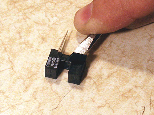
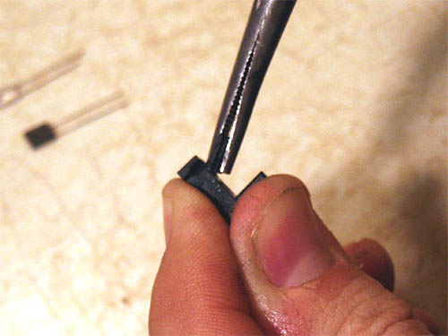
Step 30 The trick here is to safely remove the two internal components from their plastic housing without damaging them. There may be better ways, but here's how I've done it, always successfully, in the past. With your small #1 flathead screwdriver, gently pry the thin plastic coating away from the body of the housing until it breaks and you can remove it, piece by piece. The internal components are housed at the outer edges of the housing, try to avoid this area as you chip off the outer plastic. |
 |
|
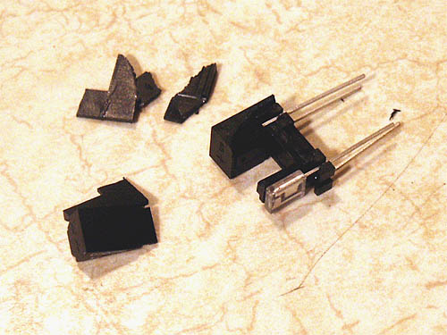
| Here, we're about halfway done. Notice that the clear infrared (IR) LED is already completely exposed. Continue removing the outer case until all that remains are the two components and the internal alignment housing. |
 |
|
|
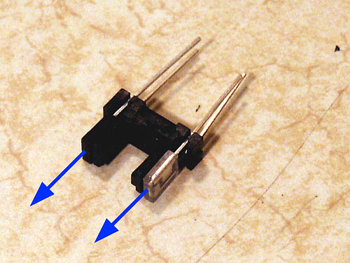
Step 31 Here's the new optocoupler with the outer covering completely removed. Slide the two components out of the alignment housing as shown. |
 |
|
| The component parts of the new optocoupler are identified as shown. The alignment housing serves a dual purpose; that of properly spacing the LED and photo diode, and also providing a "mask" for the beam transmitted from the LED to the photo diode. Without these masks, the beam path would be more susceptible to interference from outside light sources, and would provide a less accurate switching pattern. So, while we can't use the alignment housing in our application, we do need those beam masks... |
 |
|
|
Step 32 With your long-nosed pliers, grip one of the beam masks as squarely and as close to the base of the alignment housing as possible and gently break it squarely off. Repeat for the other mask. |
 |
|
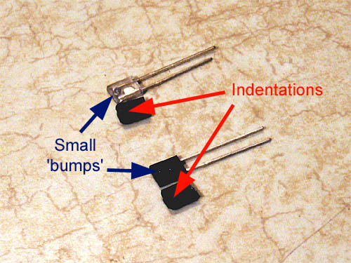
| Here's a detail shot of the devices with their masks. While it's difficult to see in these pictures, both the clear LED and the black photo diode have a small bump on one side. Once installed, these bumps must face each other to complete the light path. The beam masks, shown next to their respective devices, have a corresponding indentation to accommodate these bumps so that the masks may mount flush with the devices. The next step is to attach a beam mask to each device. |
 |
|
|
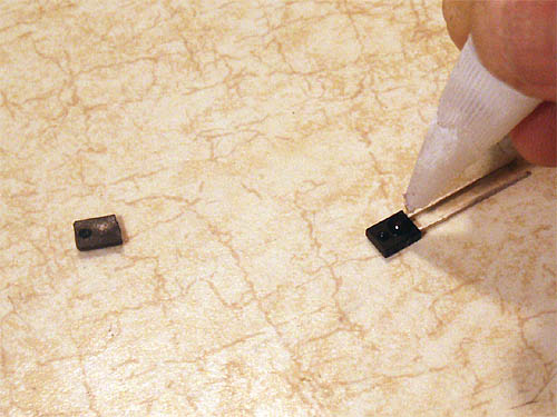
Step 33 Place a pin-head sized dab of superglue on the photo diode, just below the 'bump', and apply the beam mask. Make sure it's square with respect to the diode, and press firmly together for about 30 seconds until the glue sets. |
 |
|
|
Step 34 Repeat step 33 with the infrared LED. |
 |
|
|
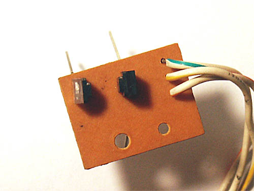
Step 35 And, of course, repeat for the second set of optocouplers. The finished devices are shown. |
 |
|
|
Step 36 Mount the first set of devices to the first optocoupler board. Insert leads for one of the IR LEDs (clear backing) into the holes designated by the |
 |
|
|
Step 37 The purpose of soldering only one lead of each device is to allow you sufficient flexibility to align the two devices. Use your long-nose pliers to gently adjust both devices so that they are parallel to each other from an overhead perspective, as shown. This alignment is not absolutely critical, but do the best you can. |
 |
|
|
Step 38 Now, ensure both devices are perpendicular to the board and thus parallel to each other from a side view. Once you're satisfied with the alignment, solder the remaining connections and clip off the excess leads. Repeat for the other set of optocouplers. It's a good practice to clean excess flux from your solder joints with some isopropyl alcohol; I find dipping a toothbrush in some, scrubbing the new joints, and blotting dry with a soft cloth works well. |
 |
|
|
Step 39 Remount the optocoupler boards to the transport assembly, being careful to remember the spacer washer for the board nearest the solenoids. Use your reference mark (from step 26) to properly align this board before screwing it down. Once both optocoupler boards are in, spin both reel hubs on the transport to ensure they move freely, and realign the optocoupler boards as necessary until they clear. |
||
|
Step 40 Use this opportunity to thoroughly clean the transport and tape heads, since the transport is easily accessible. Now is also a great time to install brand new belts and idler tires, so you won't have to take the deck all apart again in a few years. |
||
|
Step 41 Finally, reverse the disassembly steps to reassemble the deck. Fire her up, relax with a nice cold one, and listen to some old cassettes you haven't heard in a while. Congratulations! You've resurrected a fine piece of vintage audio equipment - may you enjoy it for many years to come! -Dave |
||